The magnet geometry you choose for a brushless DC (BLDC) or permanent-magnet synchronous (PMSM) rotor is one of the earliest and most consequential decisions in the motor design. It sets the air-gap flux distribution, shapes the cogging torque and back-EMF waveform, and — just as importantly — determines how the rotor is assembled, how fast it can safely spin, and what it costs to build at volume. Change the grade late in a program and you adjust a number; change the geometry late and you often redesign the rotor.
Three geometries cover the vast majority of BLDC and PMSM rotors: the arc segment, the block, and the ring. Each is a different answer to the same question, and the right choice depends on your rotor topology, diameter, speed, pole count, and production volume. This guide compares the three from a magnetics and manufacturing standpoint, and shows where each one earns its place.
Arc segment magnets: the performance workhorse
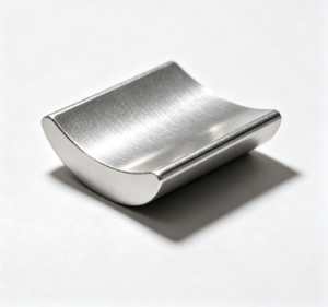
An arc segment (often called a tile) is a curved magnet that follows the rotor circumference and is bonded to the rotor surface — the classic surface-permanent-magnet (SPM) construction. Each pole is a separate segment, so a rotor is built up from as many pieces as it has poles.
The strength of the arc segment is flux shaping. Because each segment is a discrete part, the pole-arc ratio can be tuned, and the outer profile can be ground eccentric — a “bread-loaf” contour that widens the air gap toward the pole edges. This shapes the air-gap flux toward a sinusoid, which directly lowers cogging torque, smooths the back-EMF, and reduces torque ripple. Segments can be radially or parallel magnetized, and can be arranged into Halbach-like patterns for a stronger, more one-sided field. The geometry also scales cleanly to large diameters and high pole counts, where a one-piece magnet would be impractical.
The trade-off is assembly. Multiple segments mean more bonding operations, tolerance stack-up across the gaps between poles, and — critically at high speed — a retention scheme, since adhesive alone cannot hold surface magnets against centrifugal load. A carbon-fiber or alloy sleeve, or banding, is common above a few thousand RPM. Arc segments therefore suit mid-to-large diameter rotors and performance-sensitive applications: servo drives, traction, precision spindles, and any design where torque smoothness is a specification rather than a preference.
Block magnets: simple to make, essential for IPM
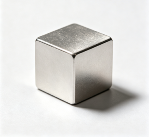
A block is a flat, rectangular magnet. On a surface rotor it can be mounted onto a faceted (polygonal) hub, but its more important role is inside interior-permanent-magnet (IPM) rotors, where rectangular magnets are inserted into slots punched in the laminated rotor stack.
Blocks are the easiest and lowest-cost geometry to produce. Straight cuts and flat grinding avoid the curved profiling that arc segments require, dimensional tolerances are tight, and uniform magnetization is straightforward. In an IPM rotor, that simple shape unlocks a great deal of design freedom. Burying the magnets in V-shape, spoke, or delta arrangements concentrates flux (so a lower-remanence grade — even ferrite — can still produce a strong air gap), adds reluctance torque, enables wide-range field weakening for high-speed operation, and mechanically shields the magnets inside the steel, which is a major advantage for high-speed rotors. This is why block-based IPM rotors dominate EV traction and high-speed industrial drives.
The limits are geometric. A flat magnet across a round air gap produces a non-uniform gap and richer harmonics unless the rotor is faceted or the design compensates. And IPM rotors introduce their own complexity — the steel bridges that retain the magnets must be thin enough to saturate magnetically yet strong enough mechanically, which is a genuine engineering balance. Blocks suit IPM traction and high-speed designs, field-weakening applications, and cost-sensitive programs where a straightforward magnet shape keeps the bill of materials down.
Ring magnets: one piece, maximum consistency
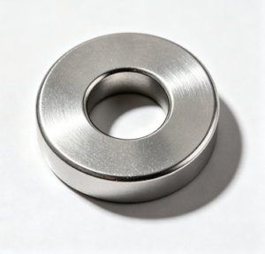
A ring is a single annular magnet magnetized with multiple poles around its circumference. Instead of assembling a rotor from many segments, the ring slips over the shaft or hub as one component.
For small motors, this is the cleanest solution available. A single part means no inter-segment gaps, no per-pole bonding, and excellent pole-to-pole symmetry — which translates into low cogging and consistent output, unit after unit, with minimal assembly labor. Concentricity is inherently good, and there is no multi-piece retention to engineer. For high-volume small motors — fans, pumps, compressors, automotive auxiliaries, and consumer products — the ring is often the most economical and repeatable choice.
The constraint is size and process. Sintered NdFeB is brittle, and producing large-diameter or thin-walled rings drives cracking and yield loss, so cost rises steeply with diameter. Radially oriented sintered NdFeB rings are particularly demanding to manufacture. Beyond modest diameters, designers typically move to bonded NdFeB rings — easier to form into complex multipole shapes, but with noticeably lower remanence — or to ferrite. Multipole magnetization also requires a dedicated fixture, and because the ring is one piece, a single crack scraps the whole magnet. Rings are therefore best for small-to-modest diameter rotors produced in volume, where assembly simplicity and consistency outweigh the size ceiling.
Side-by-side comparison
| Criterion | Arc segment | Block | Ring |
|---|---|---|---|
| Rotor type | Surface (SPM) | Surface or interior (IPM) | Surface (small) |
| Pieces per rotor | One per pole | One per pole/slot | One |
| Flux/waveform shaping | Excellent (profiled arc) | Good in IPM (via geometry) | Good (magnetization-set) |
| Cogging control | Excellent | Design-dependent | Good with quality magnetizing |
| Assembly effort | Higher (bond + retain) | Moderate (insert/bond) | Lowest (single part) |
| High-speed suitability | Needs sleeve/banding | Excellent (IPM, shielded) | Modest diameters only |
| Diameter range | Small to large | Small to large | Small to modest |
| Relative cost driver | Profiling + assembly | Low (simple cuts) | Rises steeply with size |
| Typical use | Servo, traction, spindles | EV/IPM, high-speed drives | Fans, pumps, small motors |
How to choose for your rotor
Start with the rotor topology. If the design is surface-mount and torque smoothness matters, arc segments give you the most control over the air-gap flux. If it is an interior-magnet rotor built for high speed or field weakening, blocks are effectively required and bring flux concentration and mechanical protection with them. If the motor is small, high-volume, and cost-driven, a ring removes assembly steps and delivers the best pole-to-pole consistency.
Then layer in diameter and speed. Large diameters rule out one-piece sintered rings and favor segments or blocks. High rotor speeds favor IPM blocks or well-retained segments over surface rings. Finally, weigh volume and cost: rings and blocks reward high-volume simplicity, while arc segments buy performance at the cost of assembly.
Material grade matters as much as shape
Geometry sets the field distribution, but the magnet grade sets the thermal ceiling. A rotor that runs hot needs sufficient intrinsic coercivity (Hcj) at operating temperature to resist demagnetization, regardless of whether the magnet is an arc, a block, or a ring. Our engineering team produces all three geometries in sintered NdFeB and matches the grade to the working point — and for many BLDC and PMSM applications, our Dy/Tb-free grades supply the required coercivity while shipping under standard export procedure, with a predictable 25–30 day lead time and no exposure to heavy-rare-earth price swings.
Choosing the geometry is the first decision; pairing it with the right grade is what makes the rotor manufacturable, stable at temperature, and economical at volume. If you can share your rotor diameter, target speed, pole count, and operating temperature, our engineering team can recommend the geometry and grade combination that fits your design.
Share your rotor topology, diameter, target speed, and pole count, and our engineering team will help you select between arc segment, block, and ring — and pair it with the right NdFeB grade for your BLDC or PMSM design.
Contact our team at tony@xh-magnet.com to discuss your rotor magnet requirements — we’re glad to help.